Tuesday, November 26, 2019

Cabinet Assembly Begins

It seems to have taken forever to get to this point but I am finally here - cabinet assembly.

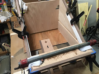
One of the things I did when dry fitting the cabinet, so I could add the trim, was to attach a piece of wood across the back to keep the cabinet upright and square.  I did not want it racking to one side or the other.  For the permanent assembly I took extra precautions by adding an addition, larger, board across the back.  After I marked and drilled some holes in the boards I then carefully held the cabinet side panels in place and secured the boards.


I then flipped the unit on its back, inserted the play field board, and snugged a bar clamp to help keep it together.  Focus then went to the two front boards - the marquee and the coin slot boards.  Before I attached either I needed to make sure they were precisely where I wanted them to be.  Had I not done that and attached one there was a good chance that the other would not align correctly.  
To do this I clamped some smaller pieces of wood to the side boards.  The two panels would then rest on these pieces of wood.  These smaller pieces of wood could then be adjusted and repositioned until I had everything exactly where I wanted them to be.


When I was happy with the positioning I simply lifted up a board, added glue, carefully placed back in place, and nailed.  Here it is with the small wood pieces removed.


At this time I also glued a piece of white pine across the cabinet's front-bottom (can be seen in the three previous pictures).  This is just part of the framing structure and will not be seen in the completed cabinet.

Once the structure's glue had set, I removed all the clamps, the temporary rack-prevention back boards, and set it up.  I also slid in the vertical coin drop board along with the two smaller side boards that sit on the play field all to give a better feel for how it was going as is shown in the following pictures.


I had already added some wood filler and, possibly noticed, is the black paint on the marquee and coin slot boards.  More with the marquee, when the speaker grills were attached it was possible to see the wood through the grills tiny holes.  Not wanting this, I applied a thick coat of black acrylic paint.  

Wednesday, November 20, 2019

Fire Up The Laser

Finally, F-I-N-A-L-L-Y!, I get to do some laser etching.  I have been (somewhat) patiently waiting for this step.  I disassembled the unit and did a lot of sanding (better to sand now, before the laser work, instead of later and risk damaging the imagery).

My design has three images that will be laser etched onto the wood.  I did several test burns, with different settings, in order to find the desired darkness.  Once that was decided it was time to light the rocket. The first is a landscape scene across the front marquee.


The marquee will contain 2 speakers for the Bluetooth receiver.  Those speakers will be covered with the black grills shown in the previous image.

Next was the bass image for the cabinet's right side panel.  The first image below shows the test burn on a scrap sheet of similar colored plywood with the second image being the completed burn on the actual cabinet item.


The bass image is about 11" wide and 17" tall.

For the opposite side I decided to do an eagle.  A little past half way through the burn the computer software locked up and the laser started acting weird.  My burns are done in 2 passes.  The image below shows the first pass complete and, in the lower left corner, where the second pass had started - making the image darker - before things went South.


I never run the laser unmonitored and was quickly able to shut things down.  The following image is a close-up of where it began burning too much.  


I regrouped, regenerated my tool path to do only the second pass, and started again.  It wound up burning that particular spot a total of three times but, overall, it is not noticeable.  The following picture shows the completed burn.


Correcting A Mistake

In my prior post I mentioned a mistake where I attached 3/4" trim instead of the desired 1/2" trim.  This caused the capping of a dado slot.  That slot is what I would use to, later, slide the coin drop backboard in.  By capping the top of it I will not be able to do that.  The two pictures below show the capped slot and the design indicating how the trim should have been.


To fix this I decided to just extent the slot into the trim.  When the top board was installed there would be a small hole on either side.  Since this will be on the top of the cabinet and not typically seen, I was not too worried about my corrective action.  I could just present it as ventilation if anyone were to ask.  :)

To cut the slot I clamped a straight edge along the existing dado and carefully made 2 cuts.  I then pieced out the rest with a chisel. 


Some Trim Work

It is time to add some trim.  With the cabinet dry fitted together I realized that I needed a way to keep it square while nailing on the trim.  My first approach was to go ahead and cut out the coin drop board.  With this in place I believed it would be enough to keep the cabinet square.


After sliding it in place I found that it was not snug enough to keep the cabinet from racking to the side.  Somewhat disappointed, I went with plan B - I squared the cabinet and temporarily screwed a scrap piece of plywood across the back. 


(That picture was taken after the trim was installed.)  This proved to be exactly what I needed so I moved on to cutting the trim boards. 

I purchased a piece of 4" x 24" x 3/4" walnut and, using my table saw, ripped some 3/4" pieces.  Then, patiently and carefully, I measured, measured again, cut, and nailed the pieces on.


The last pieces to go on were across the tops of the sides from front to back.  In a case of moving without thinking, I made a mistake and attached the 3/4" wide strips instead of the planned 1/2" strips.  This caused the dado slot - the slot that holds the coin drop board mentioned at the beginning of this posting - to be capped off.  Meaning that once the cabinet is assembled I would not be able to slide that board down and into place.


Although not ideal, I determined that I could cut that notch out of the trim and decided I would address it later.

Also, I was using an air nail gun to attach the trim.  I did have one case of a nail blowing out the side.


Following Murphy's Law, this happened on the outside of the cabinet and not the inside.  Having experience this several times in the past, I knew I could carefully remove the nail and fill the spot with putty.  Not ideal but it is what it is.

With that I will mention - when using a nail gun, if you are holding material in place with your hand keep your fingers more than a nail's length distance away from where you are nailing.  You do NOT want one of those nails deviating and going into your finger.

Friday, November 8, 2019

More Work On A Control Panel

My previous post discussed the design and layout of a control panel.  This panel houses the Bluetooth controls, a light switch, and USB ports (for phone charging).  I finalized the design and carved the final product in my walnut material.  Below are pictures of that item...

The following picture shows the back of the panel.  I had to pocket some of the material, making it thinner, so that I could physically attach the items.  The triangle shaped pins provide alignment in the board it attaches to.


The following shows it attached to the cabinet's board.


This picture shows how the alignment pins help to keep in place before secured with screws.


With the exception of a status LED, the controls are secured to the panel.