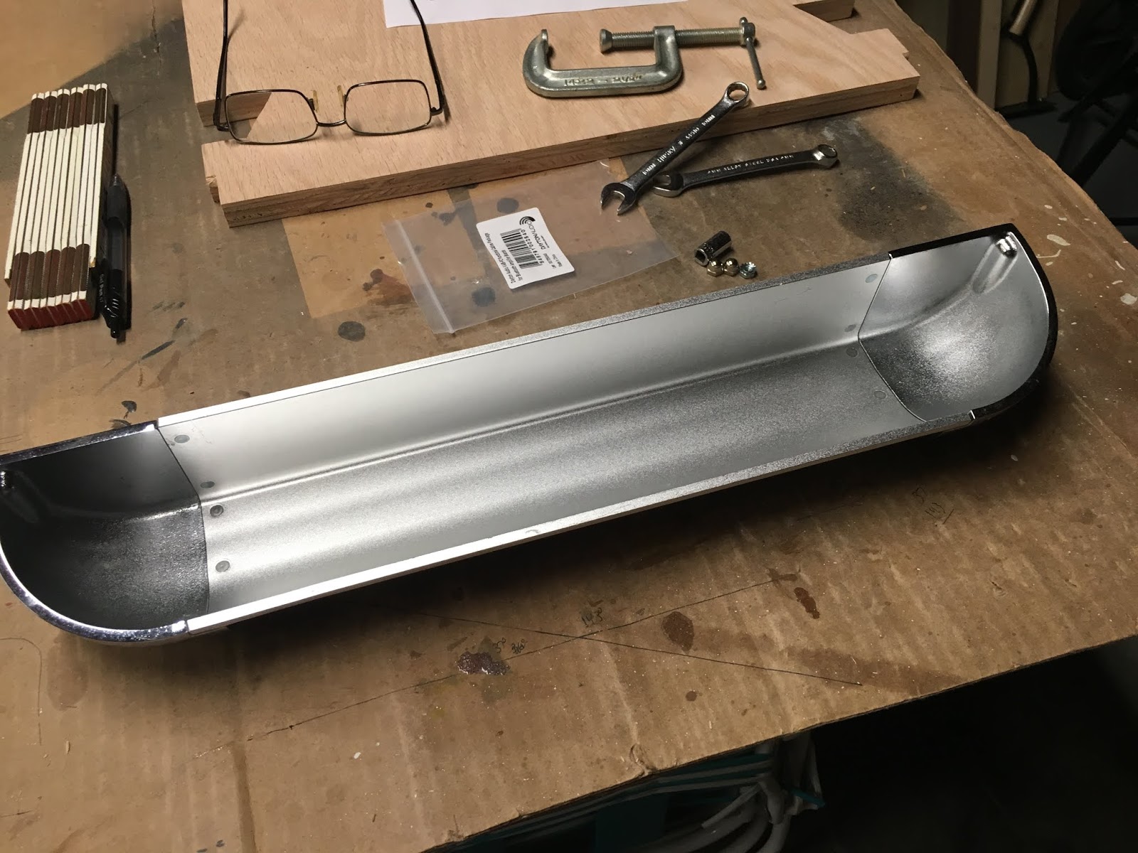
During the way early on initial thoughts of my pusher build I knew that I wanted a metal coin return tray. Not a narrow slot, rather a TRAY. I just did not know how hard it would be to find one. After tons of internet searching I found one from, I believe, AliExpress which turned out to be both impracticable and undesirable for me. I resorted to ordering one off of EBay I had noticed earlier. I was super happy it was still available.
It is geared more towards slot machines but it was the shape and metal material I wanted. Problem was it was too long. Fortunately the end caps could be easily removed and the result was definitely worth making work. Unfortunately, however, I had to re-cap those ends. To do that, I traced the edge profile on a piece of paper, scanned it in to my computer, loaded it in my design software, and completed the task by carving this test piece on my CNC.
The test piece worked perfectly. So I loaded up some walnut and did the same carve.
Placing them on the ends of the tray and then in the cabinet.
So far, so good. I felt encouraged that I was on the right track. Now to figure out the rest of the drawer.
"
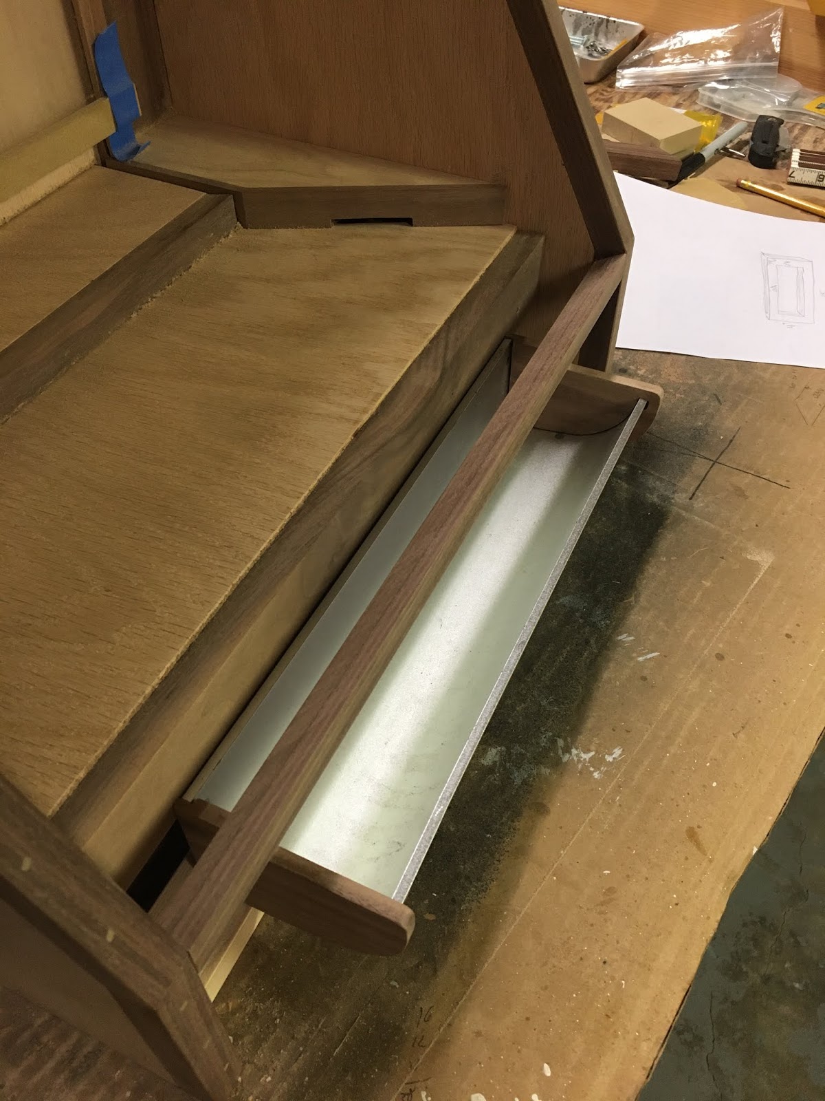
But why is is a drawer?...Why do you keep saying 'drawer'?" This drawer actually serves two purposes - (1) It holds the coin return tray for the person playing the game and, (2) It provides easy access to the coins that fall in the lose chutes. This second reason is huge in that it allows easy access to the house-winnings without having to move the cabinet and access those coins through the back. It is this dual support that has made the installation of the coin tray more challenging.
This drawer needs a front. Back to the CNC gave me this:
I then came up with this over complicated way to attaching the tray to the drawer front.
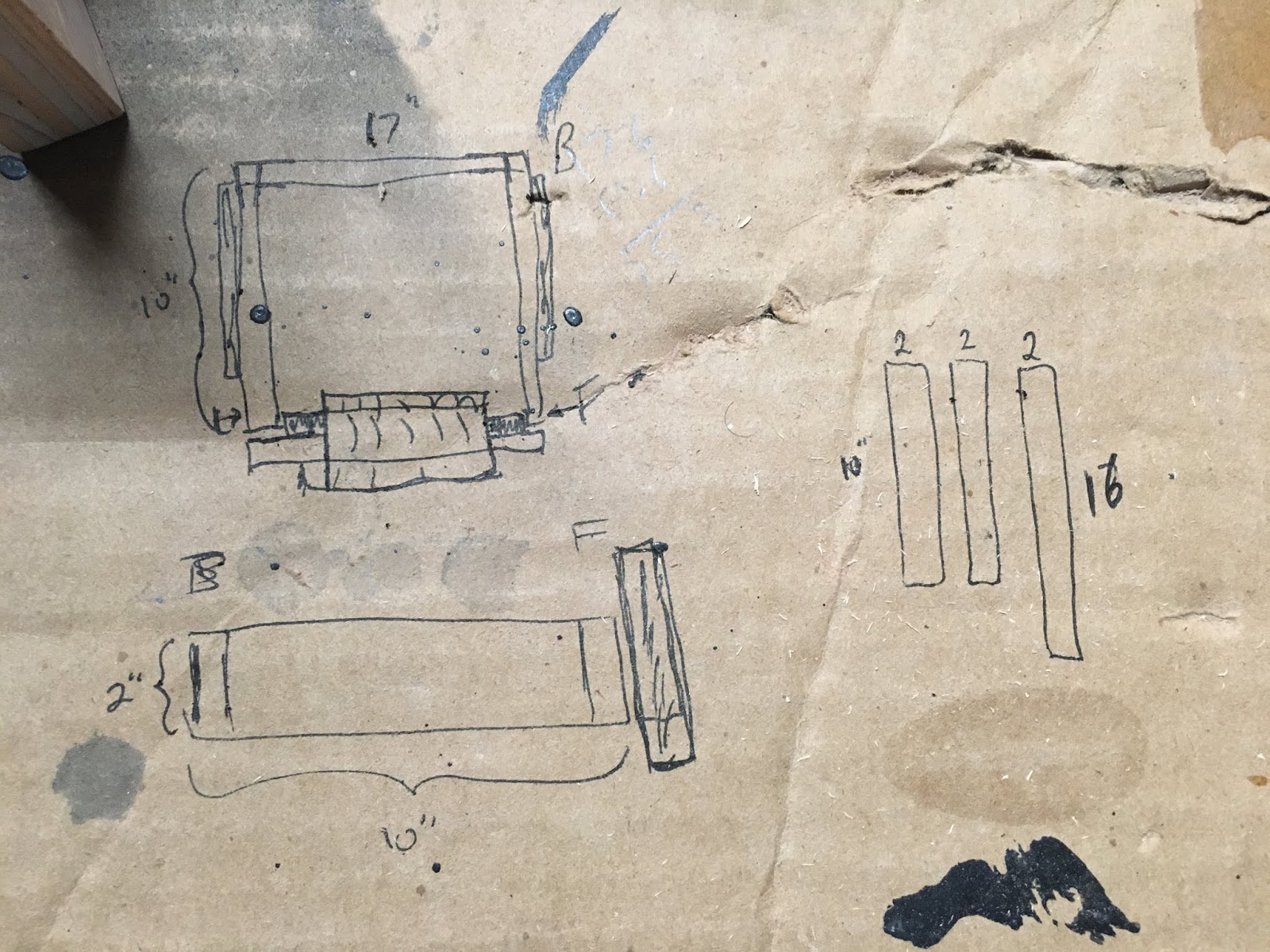
In my defense, this is more complicated than it would be if I did not want to take it back apart for stain, paint, and finish. That is the drawer front. As for the box of the drawer...a little doodling to get dimensions and cutting/nailing some wood gives me a drawer:
I attached some self-closing drawer slides and then made this video showing how it works and why:
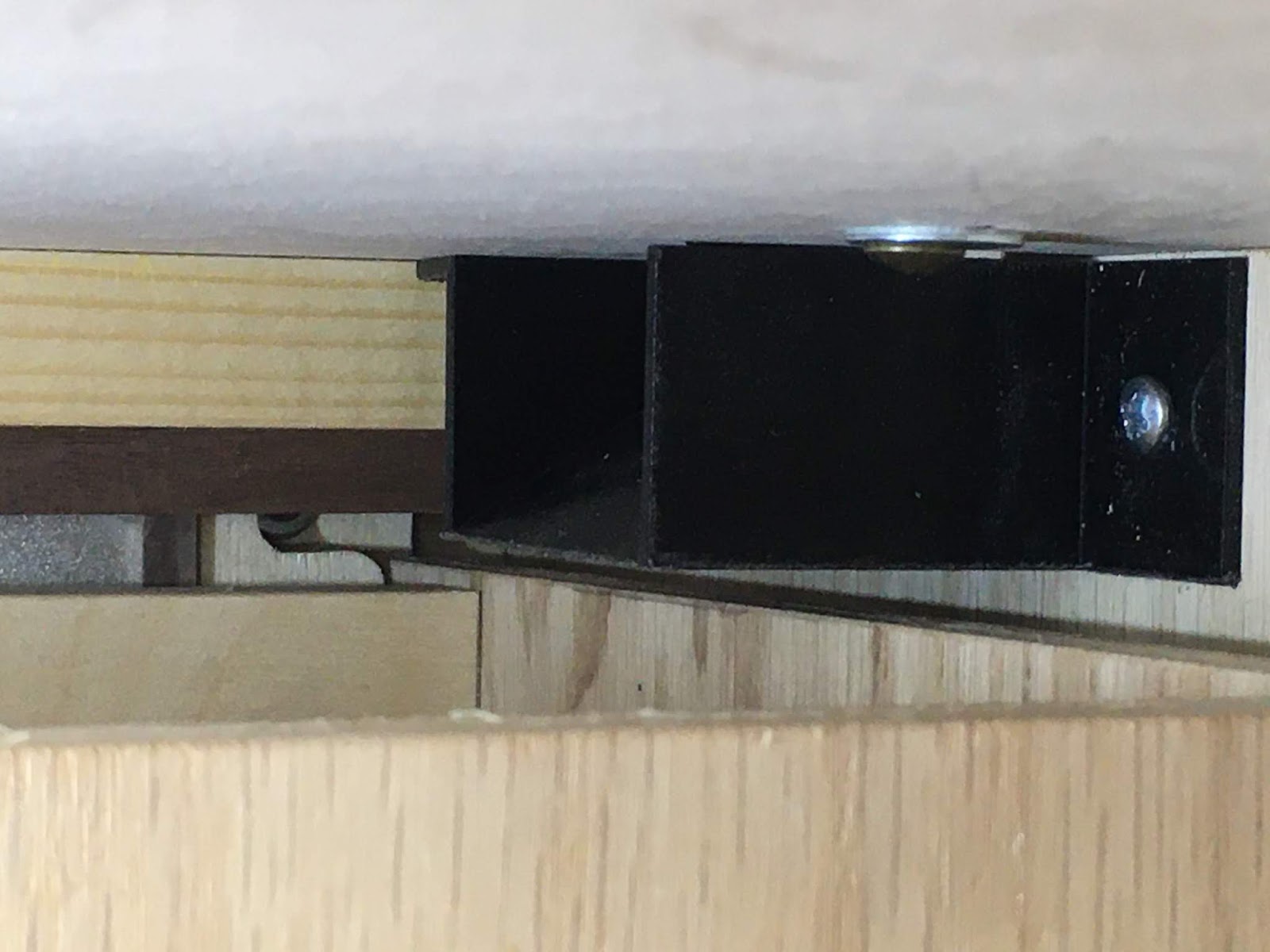
With the drawer frame done I can now address a problem with its size and construction - coins that drop from the extreme sides of the play field could drop to the side of the drawer or, worse yet, get jammed up in the drawer slide.
Knowing this would be something to address I kinda already had a plan. Back to the 3D printer I made a couple of wedge shaped pieces. On those I glued some walnut and then sanded the walnut to match the shape of the wedge. The back of the wedges have a slot that slides over a screw. If the screw is tight enough the wedge will be snug and not flop around. (One of the screws is visible in the above 2 pictures.)
And when in place:
That is all the work for the drawer itself (except for stain and paint). One additional thing, however, needed to be done for the drawer's lose chute feature to work properly. Much like the wedge slides above for the push platform dropping into the coin tray, I needed a way to make sure that coins that drop in the lose chutes make it into the drawer and not along side in jammed in the drawer slides. For that, more 3D printing. The picture below shows the underside of the cabinet where one of the lose chute holes is and how it is relative to the drawer.
A quick design and print gave me these to slides:
Here are a few pictures of them in place:
They worked great at redirecting the coins towards the center of the drawer.
That is all for now for the drawer. Stay tuned for more.